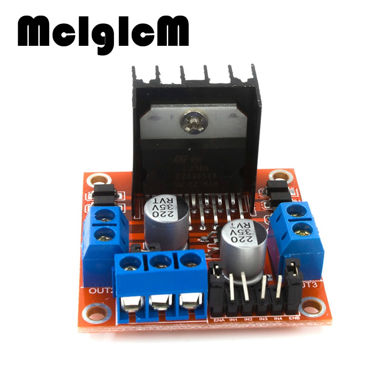
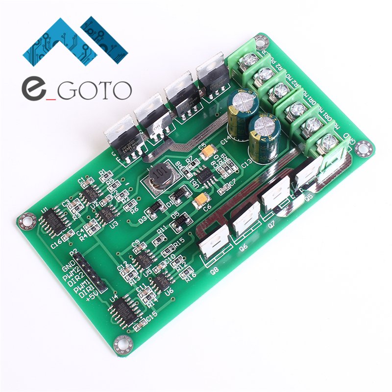
Lowest Cost H-Bridge. William chan Posts. An H-bridge consists of two current-sinking and two current-sourcing drivers. If you're designing for mass production. Driving a high current DC Motor using an H-bridge. The half-bridge driver chip is able to supply this high voltage by using a bootstrapping.
Contents • • • • • • Overview An H-bridge is a circuit configuration commonly used to control the speed and direction of a brushed DC motor. The convenience of an H-bridge is that a low current digital signal can be used to control a high current motor (or other device). Full H-bridge circuits capable of a few Amps can be purchased in convenient IC packages (see ). The H-bridge described in this write-up is capable of currents up to about 40A at 24V, but requires the assembly of a PCB.

In the circuit diagram we see that the 4 mosfets surrounding the motor form an “H” shape. The mosfets are used as switches and are activated in diagonal pairs. To apply a forward voltage across the motor, mosfets 1=4=on and 2=3=off, causing the motor to spin in the forward direction (=100% duty cycle). To make the motor spin in reverse, 1=4=off and 2=3=on (PWM=0% duty cycle).
To keep the motor stationary, forward voltage is applied half of the time and reverse voltage is applied half of the time (=50% duty). If the voltage reversals are at a high enough frequency, the cycling is unnoticeable.

Generally 20kHz is a good choice for PWM frequency because it is well beyond of the dynamic range of motors and just beyond the range of human hearing. For more information on PWM, see and.
While the concept of a high current H-bridge is fairly simple, many practical considerations complicate implementation. List of Unspecified Parts Component Value/Part# MOSFETS STP80NF55-08 (80A 55V) Half Bridge Driver IR2109 DC to DC converter VBSD1-S24-S12-SIP (24V to 12V) Regulator 78L05 (5V) Inverters SN74HC14N Optoisolator 4N270545K C_B 0.1 uF R_G 4.7 Ω R_PD 2.2 k Ω The example H-bridge above works with a 24V supply and all of the specified components. If you need to change a component, it is very likely that the other components will need to be re-sized. Some rules-of-thumb for each component are provided below. Implementation Considerations Electrical Noise The motor can create significant electrical noise because it draws a great deal of current causing dips and spikes in the power supply, and more significantly, when the mosfets abruptly cut off the current, the motor's inductance creates voltage spikes (as predicted by: V = L*di/dt).
To prevent the noise from having a deleterious effect on the mosfets, there is significant capacitance in close proximity to the mosfets. The diodes (that often come integrated into the mosfets) also play an important role here. If the motor is being driven forward (1=4=on) and then all mosfets are turned off, there will be a voltage spike due to the inductance of the motor.
This spike can dissipate by drawing current through the diodes in mosfets 1 and 3, effectively sending the current into the capacitors and battery. It is also possible to reduce the inductive voltage spikes by increasing the time it takes to transition between states.
This can be accomplished by increasing the Gate Resistance (covered later). Shoot Through It is important to ensure that the two mosfets on the same half-bridge are never on at the same time. This condition called “shoot through”, shorts the power supply and will likely damage the mosfets.
The IR2109 half bridge driver chip contains logic to prevent this condition from occurring. It outputs the PWM signal to the high mosfet gate while sending an inverted version of the signal to the low mosfet gate. To be certain that shoot through does not occur during the transient, it also adds a 540ns dead time where both signals are low.
How To Install Oblivion Mod Manager Steam. High Mosfet Gate Voltage To turn an N-channel mosfet to its “on” state, it is necessary to raise its gate voltage (Vgs) 2-10V above the source voltage (note that the pins on a N-channel mosfet are deceivingly named: the low-voltage side of the is the “source”). In our example this means that when the high mosfet is turned on the voltage at the source pin (the high side of the motor) is 24V so the voltage at the gate must be about 34V.